A belt conveyor, also known as a belt-type conveyor, is a continuous conveying machine. It uses a driving device to move an endless conveyor belt, and the belt relies on friction between its carrying surface and the material to transport bulk materials (such as ore, coal, and grain) or packaged items along a fixed path from one end to the other.
Structural Features of a Belt Conveyor
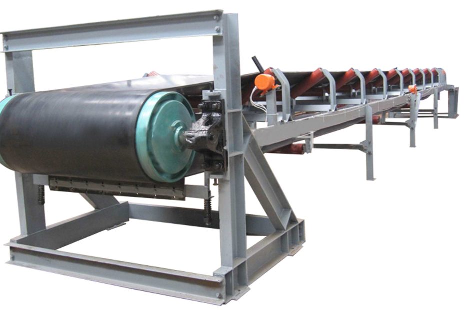
The structural design of a belt conveyor focuses on the core requirement of “continuous conveying.” The complete system typically consists of eight major components: the conveyor belt, driving device, drum assembly, idler groups, frame and supports, tensioning device, cleaning device, and loading/unloading device. These components work together to achieve stable and efficient material transport.
Conveyor Belt
The conveyor belt performs two functions: carrying materials (working surface) and transmitting traction force (via friction with the drums). Its structure directly determines the conveyor’s application range.
Structural Features
Layered composite design: Most industrial belts use a multi-layer fabric core with rubber covers.
Reinforcement layer: Cotton canvas, nylon canvas (NN), polyester canvas (EP), or steel-cord (ST), providing tensile strength. Steel-cord belts offer high tear resistance for long-distance heavy-duty transport.
Cover rubber:
- Top cover: Contacts materials and requires abrasion and impact resistance.
- Bottom cover: Contacts drums/idlers and requires aging resistance and low friction.
Special functional designs:
- Patterned belts: With raised patterns or grooves to prevent material sliding; suitable for steep inclines (>18°).
- Heat-/cold-resistant belts: Made with special rubber (e.g., silicone rubber) to withstand temperatures up to 200°C or as low as –40°C.
- Flame-resistant belts: Used in coal mines with flame-retardant additives to prevent ignition from static sparks.
Driving Device
The driving device converts motor power into belt traction. Its structure emphasizes reliable torque transmission and high load adaptability. A common configuration consists of “motor + reducer + coupling + drive drum,” or an integrated electric drum.
Structural Features
- Modular combination: Motor → reducer (speed reduction and torque increase) → coupling (flexible connection) → drive drum (torque-to-friction conversion). Components are assembled with flanges or pins.
- Protective design: Motors and reducers use IP65/IP66 protection for dusty or humid environments. Underground coal mines require explosion-proof motors.
- Integrated electric drum: Motor, reducer, and drum are enclosed in a sealed cylinder to reduce installation space.
Drum Assembly
Drums act as guiding wheels. They include drive drums (power transmission) and bend drums (changing belt direction). Both use a metal shell combined with bearing housings and require high rigidity and wear resistance.
Structural Features
Drive drum:
- Rubber coating (8–15 mm) increases friction and prevents slippage; surface patterns such as rhombic or herringbone improve grip.
- Drum shell made of Q235 carbon steel or stainless steel; shaft uses heat-treated 45# steel.
Bend drum:
- Generally uncoated or lightly coated.
- Used to change belt angle, increase wrap angle, or support the return belt.
- Types include tail bend drum, vertical bend drum, and snub drum.
Idler Groups
Idlers support the belt and material weight while reducing running resistance. Their structure must balance load capacity, smooth rotation, and belt alignment.
Structural Features (by function)
- Carrying idlers: Support the loaded belt.
- Trough idlers: Three-roll V-shape for bulk materials.
- Flat idlers: Two-roll design for packages or large lumps.
- Return idlers: Support the empty belt; usually flat or V-type to prevent belt sway.
- Self-aligning idlers: Use tapered or vertical rollers to correct belt misalignment.
- Impact idlers: Installed at loading points with rubber rings or springs to absorb shock.
- Materials: Seamless steel tubes (Φ89–Φ219 mm), maintenance-free sealed bearings, and anti-corrosion surface coatings.
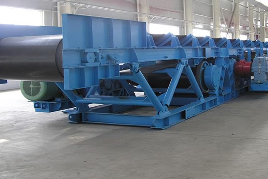
Frame and Supports
The frame and supports form the conveyor’s structural backbone. They hold drums, idlers, and the driving unit while providing strength and rigidity against belt tension.
Structural Features
- Head/tail sections: Support drive and bend drums; made from welded steel plates (≥10 mm) with foundation bolt holes.
- Intermediate frame: Connects head and tail frames; includes:Trough-type frame for the carrying side with edge guards.Flat frame for the return side.Common materials include C-steel or rectangular tubes (100×50 mm to 300×150 mm), spaced at 1.5–3 m.
- Supports:Fixed supports mounted to the ground.Suspended supports hung from roofs with steel ropes or rods to save floor space.
Tensioning Device
The tensioning device maintains proper belt tension to ensure friction between belt and drums, prevent slipping, and keep belts aligned with idlers.
Structural Features (by principle)
- Gravity tensioning: Suspended weights provide constant tension (1.2–1.5× belt force). Highly reliable but requires substantial space.
- Screw tensioning: Handwheel-driven screw adjusts drum position. Compact and low-cost; suitable for short conveyors.
- Hydraulic tensioning: Hydraulic cylinders automatically maintain tension and adapt to load changes; ideal for long-distance or variable-load conveyors.
- Electric tensioning: Motor-driven screw or drum allows remote control for automated systems.
Cleaning Device
Residual materials adhere to the belt surface and may cause misalignment or wear. Cleaning devices remove material build-up to ensure stable operation.
Structural Features
- Head cleaner: Installed below the drive drum; uses carbide or polyurethane blades.
- Return belt cleaner: Installed near the tail bend drum to clean the non-working surface.
- Combined systems:First-stage carbide blade + second-stage brush for highly sticky materials.Elastic return scrapers for improved cleaning.
Loading and Unloading Devices
The loading device ensures materials land evenly on the belt, while the unloading device controls discharge at specific positions.
Structural Features
- Material guiding device: Consists of a guide trough (a rectangular trough welded from steel plates, 1-2m in length), a set of buffer rollers (installed at the bottom of the trough), and baffles (to prevent material splashing); the width of the guide trough is slightly larger than the width of the conveyor belt (gap ≤ 50mm) to prevent material spillage.
- End unloading: Material travels with the conveyor belt to the end and falls into the hopper by gravity or the unloading baffle (simple structure, suitable for single-point unloading).
- Mid-course unloading: Uses a plow-type unloader (a liftable plow plate that scrapes material into a side hopper when inserted into the conveyor belt) or an unloading trolley (a unloading mechanism that moves along the conveyor frame for multi-point unloading). The plow-type unloader is suitable for fixed multi-point unloading, while the unloading trolley is suitable for flexible adjustment of unloading points.
Conclusion
All major belt conveyor components use standardized dimensions for quick assembly and replacement, which reduces maintenance costs. Belt conveyors support long-distance operation through intermediate drives and offer intelligent upgrades through sensors and control systems to meet diverse conveying requirements.
Belt conveyor system feature long conveying distance, large capacity, convenient maintenance, and continuous operation. They are widely used in mining, metallurgy, ports, power plants, and building material industries.