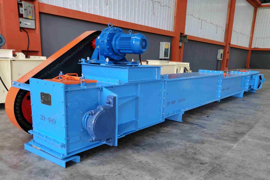
The buried scraper conveyor can convey powdery, granular and small block materials in horizontal, inclined or vertical directions, and is widely used in grain, light industry, chemical industry and other industries.
Because the scraper chain is buried in the material and moves forward together with the material when it is working, it is called “buried scraper conveyor.
When the buried scraper conveyor is working, the material enters the load-bearing section of the casing through the feed port, and is pushed by the scraper, and moves forward together with the scraper strip to form a whole. The unloaded section of the machine is returned.
The three major components of the buried scraper conveyor
The buried scraper conveyor is composed of closed scraper chain, casing, driving device and other components.
scraper chain
The scraper chain is the load-bearing traction component of the buried scraper conveyor, which is composed of many chain links connected by pin shafts and other parts. The chain links are usually welded or welded by different types of scrapers and chains, and there are also integral castings. According to the slot width, pitch size, load capacity and material properties, there are various types of chains and scrapers.
Each buried scraper conveyor can use one type of scraper, or use more than two types of combined scraper according to material characteristics. Design and manufacturing units can also design and manufacture non-standard types according to user requirements
scraper
The scraper pitch is usually equal to the chain pitch, and it can also be twice as large as the chain pitch when the working load is small. Excessive scraper pitch will cause relative slippage between materials in the trough, reduce productivity and increase power consumption, and too small scraper pitch will increase the weight of the scraper chain and increase movement resistance. Generally, the best effect can be obtained when the scraper pitch does not exceed the width of the chute.
The arrangement of scrapers (except T-type) is divided into two types: inward and outward, as shown in Figure 2-120. The outward arrangement of scrapers is at the bend from horizontal to vertical of the machine slot, and the chains in the loaded branch and unloaded branch are in harmony The partitions are in contact with each other, the operation is stable, and the noise is small; the scraper arranged outward is beneficial to observe the running state of the scraper chain, it is also convenient to maintain and replace the scraper chain, and it is also conducive to the unloading of materials; but the head and tail of the slot The structure size is large, and when the scraper transitions from the curved section to the vertical section, the space between the scrapers gradually decreases, which compresses the material and increases the resistance of the material running.
The scrapers of the two branches at the position will be in contact with the partition, the scrapers are easily damaged and cause noise, but the structure size of the nose and tail of this arrangement is small. MZ type buried scraper conveyor only adopts inwardly arranged scrapers. . Type scrapers are only available for outward facing arrangements.
The gap between the scraper and the machine tank is generally taken as about 3 times the particle size of the material, and it is generally taken as about 10mm in the grain and oil industry. If the gap is too small, the scraper is likely to collide with the side wall during operation, and the material is easily stuck between the scraper and the trough, which increases the running resistance, accelerates the wear of the scraper and the machine trough, and even causes damage to the scraper and broken chain Accidents, the gap is too large, which is not conducive to increasing the internal friction of the material and overcoming the external friction between the material and the trough, resulting in relative slippage between the material particles in the trough, and reducing the average movement speed of the material in the trough. Reduced productivity]
Generally, 2~3 cleaning scrapers should be evenly installed on the entire length of the scraper chain&The cleaning scraper is a rubber plate with the same shape and slightly larger than the scraper, and the cleaning scraper is fixed on the original scraper with screws, There is no gap between the scraper and the machine groove. When the cleaning scraper moves, the remaining materials in the machine tank can be cleaned.
the chain
The chain is the load-bearing and traction component of the buried scraper conveyor for material transportation. According to its structure, it can be divided into forged chain, roller chain and double-plate chain.
Die forged chain
Die forged chain is composed of chain rod and pin shaft. The chain rod is made by die forging, drilling, collar and other mechanical processing. When in use, the chain rods are connected together by pin shaft to form a chain. The scraper is welded on the chain bar, as shown in Figure 2-13. This chain has the characteristics of simple structure, reliable use, convenient loading and unloading, and strong adaptability to materials. The sections of the G chain bar can be designed with equal strength, so that the same strength Under the condition of the same pitch, the die-forged chain has the lightest weight. However, this kind of chain needs a special mold when manufacturing, and the amount of machining is large, and the manufacturing cost is high. It is suitable for mass production in professional factories. 2. Roller chain (GL)
Roller chains are assembled from inner chain plates, outer chain plates, rollers and pin shafts, as shown in Figure 2-13U. When this chain is in operation, the teeth of the sprocket mesh with the rollers, and the rotation is flexible, which can reduce wear and tear. ,Extended service life. Movement resistance is reduced as the rollers run on the rails. This chain structure is simple, can manufacture with common mechanical equipment, but its weight is bigger, must change in pairs when dismantling and changing chain.
Roller chain
Roller chains are assembled from inner chain plates, outer chain plates, rollers and pin shafts. When this chain is in operation, the teeth of the sprocket mesh with the rollers, and the rotation is flexible, which can reduce wear and prolong service life. Movement resistance is reduced as the rollers run on the rails. This chain structure is simple, can manufacture with common mechanical equipment, but its weight is bigger, must change in pairs when dismantling and changing chain.
Double plate chain
The double-plate chain is made of two steel plates that are stamped and formed, welded or joined to form a chain rod, and then connected by a pin shaft. This kind of chain has simple structure, easy manufacture, low price, convenient assembly and disassembly, large pitch, strong bearing capacity, and the disadvantage is that it cannot be designed with equal strength, has the largest self-weight, wears faster than the point, and has a short service life. The functions of each part in the chain are different, so different materials and different processing techniques should be selected. The pitch of the chain should be selected according to the width of the slot.
Chassis
The casing of the buried scraper conveyor can be divided into head section, tail section, feeding section, middle section, transition section, etc.’
Nose section
The nose section is composed of two parts: the head shell and the head wheel shafting. The cross-section of the head shell is rectangular, welded with 4.5 ~ 8mm thick steel plate. The front end of the head shell of MS type and MZ type is sealed with an end cover plate, the rear end flange is connected with the transition section, the upper part has an observation port, the lower part has a discharge port, and the supporting plates for installing the bearing seat are welded on both sides The middle part of the housing is equipped with a chain release plate, a support guide rail and a scraper knife. The chain release plate and support guide rail are used to assist the chain to wind out of the sprocket conveniently, and the scraper extends into the groove of the head wheel (for die forging chain and double-plate chain), then “clear the scraper chain belt to the accumulation port in the wheel groove of the head wheel. Create wheel groove material,
The head wheel shaft system mainly includes the head wheel, head wheel shaft, bearings, bearing seats, fastening parts and seals on the shaft, etc., and is connected with the transmission chain, the small sprocket and the driving device through the large sprocket on the extended end of the head wheel shaft .
The head wheel is characterized by a large tooth pitch and a small number of teeth. Generally, there are 8 to 12 pairs of forged chains and double-plate chains. The teeth have special tooth shapes, called fork teeth. The grooves of the fork teeth are used to hold the chain rods. The protruding parts of the chain rods make contact, transferring the circular force of the sprockets to the chain.
Tail section
The tail section is mainly composed of three parts: the tail housing, the tail wheel shaft system and the chain tensioning device. The tail shell is a rectangular section shell welded with 4.5-8mm thick steel plates, and the rear end is sealed with an end cover. The front flange is connected with the feeding section, the upper part has an observation port, the lower part is welded with steel plates, and the two sides are welded into two closed cavities. Bearing housings, chain tensioning devices, upper and lower guide rails, sliding plates and other components are installed in the cavity. The outermost sides of the two cavities are sealed with cover plates, and only two adjusting screws parallel to the tail shell protrude from both sides. For ease of operation, the tail shaft system mainly includes the tail wheel, the tail wheel shaft, bearings, bearing housings, fastening parts and seals on the shaft, etc. The bearing seat is placed between the upper and lower guide rails and connected with the adjusting screw. The shafting of the tail wheel can move with the movement of the adjusting screw, so as to facilitate the stretching or loosening of the scraper chain. The adjusting screw is equipped with a locking nut. After adjusting the tightness of the chain, the locking nut of the adjusting screw must be tightened to prevent the chain from loosening.
There are two types of tail wheels: one has grooves on the wheel surface, which is used for forging chains and double-plate chains; the other is a smooth surface with wider wheels but no grooves, which is used for sleeves. For roller chains, the number of tail wheels can be 1 to 2 depending on the type of chain and the number of rows, and the diameter of the tail wheel is generally smaller than the diameter of the head wheel to reduce the height of the tail section. The bearing of the tail wheel shaft adopts double-row radial spherical bearings, which can be adjusted automatically.
The tensioning device can be divided into screw type, spring screw type, falling weight type and so on.
The screw-type tensioning device relies on manual rotation of the screw for tensioning. Since the tension of the traction member of the conveyor cannot be kept constant during work, but changes frequently, it must be checked and adjusted regularly. During the adjustment, the traction member is “over-tensioned” ” and the possibility of no automatic adjustment in case of accidental overload, etc., are the disadvantages of this tensioning device. The advantages of this tensioning device are small size and compact structure.
The pendant tensioning device can automatically keep the tension of the traction member constant during the working process, but the structure is huge and complicated, and it is suitable for large-scale long-distance buried scraper conveyors.
Feed section
The feeding section is divided into A-type and B-type, and the corresponding feeding ports are called A-type feeding port and B-type feeding port respectively. The A-type feeding port is in the form of upper feeding.
The material enters the unloaded branch from the top plate of the casing, and falls through the scraper chain running on the return trip to the loaded branch at the lower part of the casing. The structure of the A-type feeding section is simple, but the scraper chain The running speed of the machine should not be too high, otherwise it will easily cause material accumulation at the tail.
The B-type feeding port is a feeding form on both sides (usually the downward inclination angle is 55”).
The material directly enters the loaded branch at the lower part of the shell from the slopes on both sides, and does not have any contact with the scraper chain on the return journey. This kind of feeding section The structure is more complex, but it avoids the crushing of the material in the no-load branch.
For general bulk materials, as long as it does not adhere to the inclined plate on the side wall of the feeding port, the B-type feeding port should be preferred.
Only when the moisture content of the material Type A feed port is only used when it is large, has strong adhesion, and poor fluidity.
Middle section
The middle section of the casing can be freely selected and combined according to the conveying distance and lifting height allowed by each model. The middle section can be divided into horizontal middle section, vertical middle section, plane ring type and vertical ring type middle section. kind
The horizontal intermediate section undertakes the function of horizontal conveying or supplying materials for the vertical conveying section. When the conveying inclination angle is smaller than the internal friction angle of the material to be conveyed, the casing can be made into a type without partitions.
When the conveying inclination angle is large or used as a feeding section, a partition should be installed between the two branches in the casing. A beam made of angle steel is installed at a certain distance in the horizontal section of the partition, and a guide rail is installed on the beam to carry the chain of the return branch.
The clapboard or supporting guide rail in the horizontal intermediate section shell divides the shell into upper and lower parts, the lower part is the loaded branch, and the upper part is the unloaded branch. Multiple discharge openings can be opened on the bottom plate of the middle section of the MS type as required.
There is a partition in the vertical middle section shell, which divides the shell into two parts, the loaded branch and the unloaded branch. Usually, the thickness h of the unloaded branch barrel is ~15mm larger than that of the loaded branch, which is used to reduce the collision between the scraper chain and the machine groove. The connecting ports of the slots of the two branches should be staggered to maintain the straightness of the cabinet after installation.
Transition section
- The transition section from the nose section to the horizontal middle section. Due to the installation of the head wheel in the horizontal nose section, the height of the machine shell is higher than that of the horizontal middle section. For this reason, a transition section needs to be installed in the middle to connect the nose and the horizontal middle section together.
- The curved transition section from the horizontal section to the vertical section. The shell of the curved transition section is divided into upper and lower parts, the lower part is the load-bearing shell, and the upper part is the unloaded shell, separated by a curved partition in the middle.
On the side of the curved partition near the load-bearing section, the guide rail made of No. 45 flat steel is fixed by spot welding. The number of guide rails depends on the inward and outward directions of the scraper and the number of chain rows.
The empty shell is on the lower horizontal end flange. There are also one or two horizontal guide rails installed to control the position of the stroke scraper chain so that it can enter the lower horizontal section smoothly. Inspection holes and discharge holes should be set above and below the curved transition section to facilitate maintenance and maintenance. Exclude material. - The upper turning transition section from the vertical section to the horizontal section. The transition section is divided into three parts: the casing of the upper slewing section, the shafting of the guide wheel and the shafting of the supporting wheel. The shell of the upper slewing section is composed of an empty shell, a load shell and a return hopper. There is an intermediate partition between the empty shell and the bearing shell, which completely separates the two shells.
The idle shell is equipped with supporting wheel shafting and supporting guide rails, which guide and support the return scraper chain. The supporting wheel can be a toothed sprocket, or a toothless light wheel or supporting wheel.
Among the wheels of the buried scraper conveyor, the diameter of the guide wheel is the largest, because the angle of rotation of the scraper chain at the upper turning section is 90°, so at least 4~5 sections of the scraper chain must be attached to the guide wheel In order to generate enough friction to drive the guide wheel and the shaft to rotate, and at the same time reduce the additional bending moment on the chain.
Supporting wheel and guide wheel shaft system is composed of supporting (guiding) wheel, wheel shaft, bearing seat, double row radial spherical bearing, end cover and sealing gasket. The material of supporting wheel and guiding wheel is usually the same as that of the head wheel.
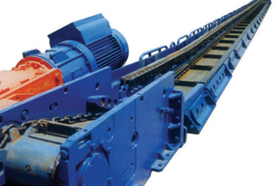
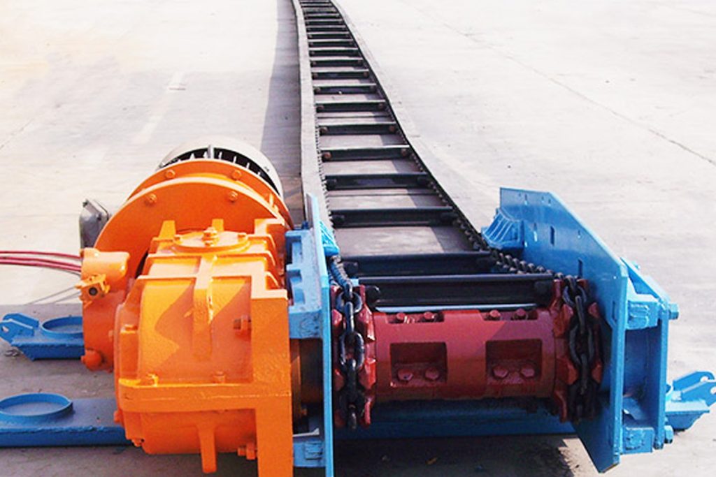
Driving device
The driving device of the buried Scraper conveyor is an independent general-purpose component, usually composed of a motor, a reducer, a pin coupling, a transmission chain, a large and small sprocket, a guard, a bracket, etc., see Figure 2-29.
The motor is directly connected to the high-speed shaft of the reducer through a pin coupling, and the low-speed shaft of the reducer is connected to the head wheel shaft through an open chain drive.
The reducer mostly adopts a horizontal single-stage cycloidal reducer & the coupling also uses a hydraulic coupling, which can be used as an overload protection device to cut off the transmission of power when the speed is reversed, so as to stop the spinning of the machine parts.
Damaged, open chain transmission usually uses sleeve roller chain. Its structure and working parameters are the same as those of general chain transmission.
The driving mode of the buried scraper conveyor is left-mounted, right-mounted and self-contained.
Standing at the tail of the conveyor and looking forward along the moving direction of the scraper chain, if the driving device is arranged on the left side of the head, it is left-mounted, and if it is arranged on the right side of the head, it is right-mounted, neither on the left nor on the right , But the one installed on the middle shell is self-contained * The mobile buried scraper conveyor must be self-contained, and the driving mode of the fixed buried scraper conveyor can be selected arbitrarily according to needs.
The function of the driving device is to transmit the power of the motor to the scraper chain mouth. The function of the tensioning device is to maintain the initial tension of the scraper chain.
In summary
The scraper conveyor is an efficient, reliable and durable material conveyor system.
It has good sealing performance, high work efficiency, energy saving and environmental protection, and is often used in coal mines, metallurgy, building materials, chemical industries and other industries.