The vibrating feeder uses the rotation of the eccentric block in the vibrator to generate centrifugal force, so that the movable parts such as the screen box and vibrator make forced continuous circular or approximate circular motions. The motor drives the active shaft through the V-belt, and then the gear on the active shaft meshes with the passive shaft to rotate. The active and passive shafts rotate in opposite directions at the same time, causing the trough to vibrate and the material to flow continuously, thus achieving the purpose of conveying materials.
Vibrating feeder is widely used in crushing and screening combined equipment in metallurgy, coal mining, mineral processing, building materials, chemical industry, abrasive and other industries.
Three major installation methods of vibrating feeder
Vibrating Feeder: Working Principle and Installation Methods
The vibrating feeder operates by using the rotation of an eccentric block inside the vibrator to generate centrifugal force. This force drives the screen box and vibrator to perform continuous circular or near-circular motions. The motor transmits power to the driving shaft through a V-belt, while the driving shaft’s gear meshes with the driven shaft’s gear to rotate in the opposite direction. As both shafts rotate simultaneously, the trough vibrates continuously, causing the material to flow steadily and achieve efficient conveying.
Three Major Installation Methods of Vibrating Feeder
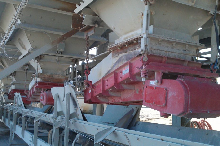
Suspension Installation
The suspension type includes several forms, each with unique features.
- Wire Rope Suspension :This method offers high reliability and stability. The wire rope rarely loosens and maintains flexibility, which reduces vibration noise. Therefore, it is widely used in industrial setups. However, adjusting the rope length is inconvenient and time-consuming.
- Suspension Rod Installation:The suspension rod design is simple and requires fewer components. Yet, the adjustment range for rod length is very limited, and friction between parts often generates noise during operation.
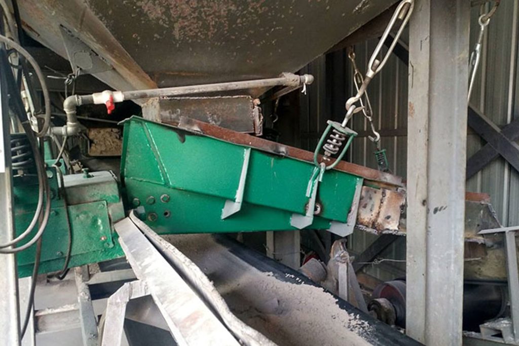
- Basket Screw Suspension:This method allows convenient length adjustment, but the basket screw tends to buckle easily. Its reliability is lower than the previous two methods, and the increased number of parts makes it more prone to noise.
During installation, the upper ends of the two front shock absorbers usually open outward at an angle of about 10°. This setup enhances the feeder’s operational stability and reduces unwanted vibration during continuous feeding.
Seat Installation
The seat installation method eliminates the need for suspension rods or auxiliary parts. Operators can install the feeder directly on a concrete foundation or on the steel structure base. Once installed, the equipment operates with high stability. However, it is essential to ensure that the foundation surface remains level and firm to avoid vibration distortion or misalignment.
Seat-Hanging Mixed Installation
This hybrid method combines the stability of the seat installation and the flexibility of the suspension type. It is particularly useful in cases where site conditions require both structural adaptability and vibration damping performance.
Installation Angle and Material Flow
The vibrating feeder usually operates with its discharge end tilted downward by about 10°. For materials that are difficult to transport, operators can slightly increase the tilt angle. However, the maximum downward angle should not exceed 15° to maintain efficient feeding and prevent material blockage.
Configuration of the Nozzle
The feeder typically receives materials directly from a silo or hopper. The material column’s pressure inside the silo significantly affects the trough’s amplitude and the feeder’s normal performance. Therefore, engineers usually install an inclined nozzle at the bottom of the silo—especially for large and medium-sized feeders—to reduce the impact of silo pressure on the vibrating trough.
To minimize wear on the inner surfaces of the trough, side baffles are installed and connected to the nozzle. The opening diameter D of the silo mouth should be determined by the maximum particle size of the material and the desired material layer thickness.
To ensure that the trough vibrates freely, a certain clearance must exist between the feeder trough, the nozzle wall, and the side baffles. The recommended gaps are:
- A: 20–30 mm
- C: 20–70 mm
- E: 10–30 mm
Smaller feeders use the lower range, while larger feeders require larger clearances.
Additionally, to prevent the side baffle from blocking the material’s movement toward the discharge end, the bottom edge of the baffle should form a small outward angle from the rear to the discharge end.
It is also advisable to install a gate at the silo discharge port. The gate allows operators to adjust the material layer thickness or completely close the outlet during equipment maintenance.
vibrating feeder:Five Key Installation Requirements
- Install the vibrating feeder as a complete unit whenever possible to ensure stability and alignment.
- If site conditions require separate installation of the trough and vibrator, tighten the connecting bolts carefully during reassembly to prevent vibration loosening.
- For suspended feeders, ensure that all four shock absorbers are evenly adjusted to maintain balance and reduce lateral vibration.
- Secure all anchor bolts firmly before operation and recheck them after test runs to ensure stability.
- Keep a proper distance between the feeder and surrounding structures to prevent collisions during vibration.
Conclusion
By following proper installation methods and maintaining appropriate structural clearances, the Vibrating feeders can operate smoothly and deliver materials continuously and uniformly.