Belt conveyors are the unsung heroes of material transportation, ensuring seamless movement in industries ranging from manufacturing to logistics. The intricate structure of a belt conveyor plays a pivotal role in its smooth functioning.
Top 2 Frame Options for Belt Conveyors
- Stringer Frame: The stringer frame, crafted from shaped steel or bended steel plates, forms the core structure of many belt conveyors. Its cost-effective design makes it a preferred choice for conveyor systems utilizing lightweight resin conveyor belts. Moreover, aluminum die casting frames are often used with resin conveyor belts due to their lightweight and durable nature. While the stringer frame is economical, its strength is not as high as its truss counterpart.
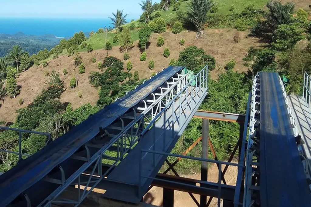
- Truss Frame: The truss frame, characterized by its use of shaped steels, is chosen when elevated frame strength is a requirement. Its application is ideal in scenarios where factors like increased ground clearance, wide leg installation intervals, and maintenance access corridors are essential. Truss frames are not only utilized in rubber belt conveyors for heavy-duty transport but also in apron conveyors, a type of chain conveyor. Though relatively costlier, the truss frame offers superior strength, making it indispensable in demanding industrial setups.
The five basic structures of belt conveyors
- Head Pulley (Head Roller): Positioned at the conveyor’s tip, the head pulley serves as the driving force. The conveyor belt moves forward as this roller rotates, allowing materials to be transported seamlessly.
- Tail Pulley (Tail Roller): The tail pulley, situated at the opposite end of the conveyor, complements the head pulley. Both pulleys collaborate to wind up the conveyor belt, ensuring a continuous motion.
- Snap Pulley (Snap Roller) or Snub Pulley (Snub Roller): Underneath the conveyor, around the head pulley, the snap pulley is strategically placed to prevent slippage of the belt wound around the head pulley. This roller adjusts the winding angle, maintaining the belt’s grip.
- Carrier Roller or Conveyor Plate: The carrier side of the conveyor holds the object-laden belt. This can be achieved through two methods: steel plates or rollers. The steel plate, also known as the sliding plate or conveyor plate, offers stability and support. Alternatively, carrier rollers are used, providing a smoother movement for the carrying side.
- Return Roller: On the return side of the conveyor, the return roller holds the belt as it makes its way back to the starting point. This roller ensures consistent tension and guides the belt’s trajectory.
A Holistic Perspective: The Interplay of Components
The structure of a belt conveyor seamlessly integrates these components to create a harmonious and efficient system. The frame forms the structural backbone, providing stability and support. The pulleys, be it head or tail, drive the conveyor’s motion while maintaining the tension in the belt. The snap and carrier rollers contribute to the belt’s functionality, ensuring proper movement and grip. The return roller completes the cycle by guiding the belt back to the starting position, ready for the next cycle.
Conclusion
The structure of a belt conveyor is a symphony of components working in unison to facilitate the smooth movement of materials. From the robust frame options of stringer and truss frames to the pivotal pulleys and supporting rollers, each element plays a crucial role.
Understanding this structure equips industries with the knowledge to optimize conveyor system design, enhancing operational efficiency and ensuring the seamless transportation of materials across diverse industries.